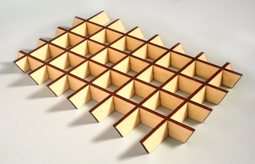
With the
use Google sketchup and the slicemodeler plugin its possible to create laser
cut 3D shapes that snap together without glue.
What you
need:
·
Google stetchup
Step 1:
Install sketchup and plugins
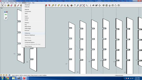
Download
and install sketchup, then download the svg export plugin and the slice
modeller plugin.
Start
sketchup. I use the "Product Design and Woodworking - Millimetres
template"
Install
the slice modeler and svg export plugins in google sketchup: Window >
Preferences > Install Extension. Navigate and select the rbz plugin files.
Step 2:
Experiment with different size nodes
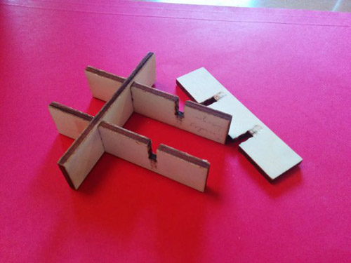
The
glue-less design is achieved by placing small curved bumps (nodes) in each
slot. The curve of the bumps allow the parts to slide together but provide
enough pressure on the material to fit together snugly. There are multiple
factors that will influence the size and number of the nodes, including slot
length wood thickness and wood density.
I
highly recommend creating parts with different size and numbers of nodes so you
can find the best fit that works for you. You might want a very hard fit that
needs to be tapped together with a rubber mallet or you might want a fit that
can be assembled by hand without any tools. The only way to find the fit that
works for you is try different size nodes. See this article for more about
nodes.
What
worked for me:
My
trivets are made out of 4mm Italian poplar Plywood and I found that a single
node 5mm wide and having a 0.16mm bulge made a good fit, that could be snapped
together by hand. However different materials will need different node sizes
and you need to figure out what works for you.
Next
we'll create a test object in sketchup to test how various size nodes work with
your chosen material.
Step 3:
Create a test object in sketchup
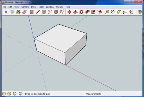
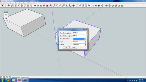
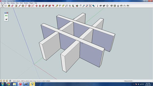
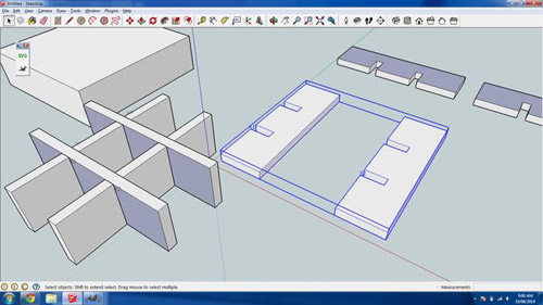
My test
object is 2cm high and 7cm wide and 7cm long. Using a square test object shape
means all the slices will be the exactly the same. A test object of these
dimensions should be enough to gauge how well the different size nodes work.
The height is the most important factor to get right. So make sure you create a
test object with the same height as your end goal design.
Open
sketchup and create a square 7cm by 7cm and extrude it 2cm up.
Now its
time to slice it up. Select the object and convert it to component by selecting
all (ctrl-A) right clicking on the object and select "make
component". Leave the component name as the default one.
IMPORTANT
sliceModeler changes the model it's slicing so make sure to make a copy of it.
To do this select the model and copy and paste a copy (ctrl-c ctrl-v).
To
slice the model select the component and open the sliceModeler dialogue
(plugins -> sliceModeler). In the sliceModeler dialogue set:
·
slice spacing of 20mm
· slice thickness to the thickness of your material, in my case the
Italian poplar is 4mm thick.
·
slice orientation to X
·
Leave other settings as the default.
Click
ok and say yes to "adding a number to each slice" and yes to leave
the original hidden. For the Y orientation dialogue leave everything as default
and click yes to "leaving the original section hidden". Click yes to
"make flatten copies", leave minimum gap as default. You now have
flattened slices and an "assembled" model to work with. Next step
we'll add the nodes to a slice.
Step 4:
Adding the nodes to a slice
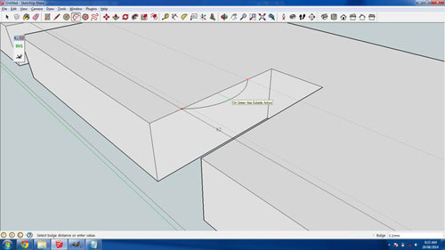
It time
to add the nodes to a slice. I find it easiest to work in a new sketchup file.
Since this model is square all slices are the same so you only need to copy 1
slice. SliceModeler exports the 4 slices as 2 groups. To copy a single slice
double click on the group to edit the group and click on a single slice. Double
check the whole slice is selected and copy it (ctrl-c). Open a new sketchup
window (ctrl-n) and paste your slice in (ctrl-v).
Zoom
into your slice and select the top down view. Your slice should be positioned
as per the image above.
The
node we will create will be 5mm long and have a bulge height of 0.16mm. Click
on the tape measure tool and drag a guide from the left edge of the slice and
set it's distance to 2.5mm. Now create another guide and set it's distance to
7.5mm. Using these guides will ensure the node length is 5mm. Next we'll create
the node bulge.
Zoom
right into one of the interlocking slots in the slice and use the orbit tool to
view the gap at an isometric angle as pictured above. Select the arc tool and
create an arc between the two guides as pictured. Make sure the arc is
orientated along the green axis. The line in the arc will change green to
indicate you are on the right axes. Set the bulge height to 0.16mm. IMPORTANT
to create a continuous outline vector for the laser cutter you need to delete
the line behind the arc as pictured. Now repeat the arc for the other side of
the slot and the same again for the 2nd slot.
You
will now have a slice surface with 2 slots and 4 nodes that can be exported to
an svg.
Step 5:
Exporting the slot into inkscape
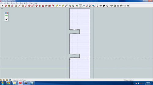
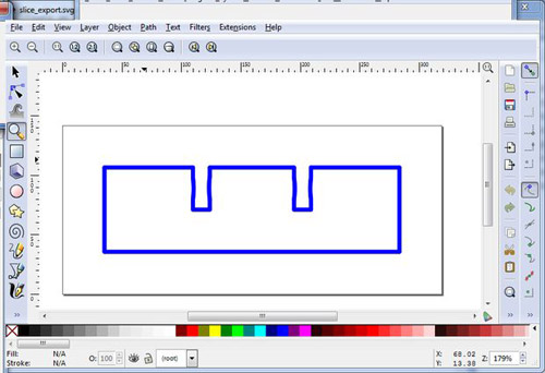
To
export the slice svg out of sketchup select the top down view and select none
(ctrl-T) then select the surface you just created the nodes on (it will be the
top surface). The selected surface will be covered with small dots. Now export
the svg by clicking on the flight of idea SVG icon. Deselect "export
annotations for faces" leave everything else as default, enter a filename
and click ok. Open the file in inkscape and you will see the outline of the
slice as per the screen shot.
Step 6:
Adding the svg to a laser cutting template
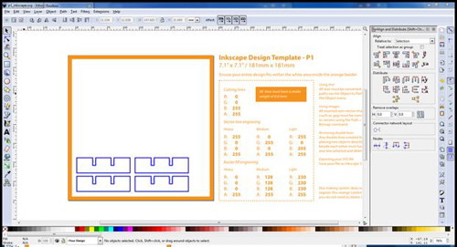
I use
ponoko's laser cutting service to cut my test slices. If you use a different
laser cutting service follow their instructions. For the rest of this step I'll
be talking about ponoko's inkscape template. Download ponoko's inkscape
template from here. I used the p1 18x18cm size template. Open the exported
slice svg in inkscape, select all (ctrl-A) and copy (ctrl-C). Open the ponoko
inkscape template and paste the slice (ctrl-v). Because the test object is
square you can simply paste in three more slices so you have a total of 4.
Arrange the four slices into a rough 2x2 grid. You want the slices all nicely
spaced and aligned so its less movement for the laser. Open inkscape's align
and distribute dialogue (shift-ctrl-A) select the left 2 slices and click
center on vertical axis do the same for the right 2 slices. Do a similar thing
but horizontally. The end result is 4 nicely aligned slices as per the
screenshot.
Ponoko
is very specific about the template's cutting line color and stroke width. For
cutting lines the line color must be solid blue and have a stroke weight of
0.1mm. To set the correct color and stroke weight, open the fill and stroke
dialogue, select all (ctrl-A) and double check the stroke paint is R:0 G:0 B:255
A:255 and in the stroke style tab set the width to 0.01mm. The cutting lines in
the template should be barley visible. Before uploading the template to ponoko
do a sanity check of the cutting vectors. The easiest way to do this is select
outline display mode (view -> display mode -> outline) and zoom right
into each vector and make sure there are no gaps that will result in an unclean
cut.
Your
done! Your now ready to upload the template to ponoko for cutting! However I
see much more space in the template for slices with different node sizes. In
the next step I'll discuss experimenting with different node sizes.
Step 7:
Expermenting with different node sizes
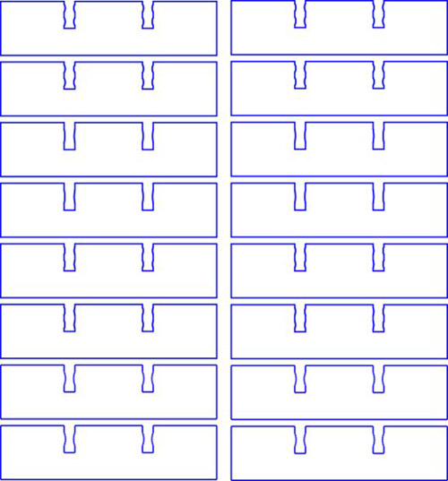
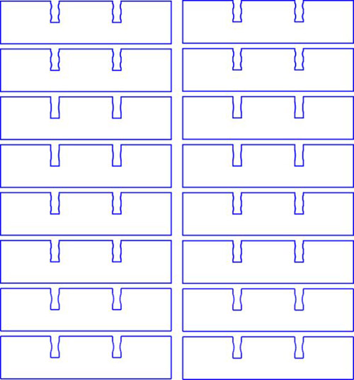
The
ponoko template has enough room for 16 slices, so in a single cutting order you
can create 4 test objects each with different node sizes. In the pictured file
I create 4 test objects with the following node configurations:
·
single node with bulge height of 0.4mm
·
single node with bulge height of 0.2mm
·
double nodes with bulge height of 0.4mm*
·
double nodes with bulge height of 0.2mm*
(A
double node is where you have 2 smaller nodes in a slot, this gives better
stability then a single node but its harder to assemble).
With
the 4mm Italian poplar I found the 0.4mm single node too hard to assemble by
hand. I also found the two double node test objects too hard to assemble.
I did
find the 0.2mm possible to assemble by hand but it was a touch harder then I'd
like, so I dropped the node bulge to 0.16mm. And when I received my next ponoko
order the 0.16mm bulge height was quite easy to assemble by hand. It also
provided firm interlocking parts that "click" together. Now back to
your test object(s).
Step 8:
Assembling the test objects
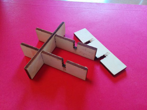
Once
you have received your order from ponoko your now ready to assemble the test
objects. But first write on each slice which node configuration it is, as its
easy to forget. Now attempt to assemble each test object while taking notes on
how hard or easy it is to assemble. If you find the right balance between ease
of assembly and "fit" then your done. Otherwise if none work, take
note if the fit is too loose or tight and repeat the process.
Congratulations! You can
now make awesome interlocking laser cut products that can be hand assembled and
don't require any glue!
~~~~~~~~~~~~~~~~~~~~~
Published By
Rajib Dey
~~~~~~~~~~~~~~~~~~~~~
No comments:
Post a Comment